![]()
Who We Are
Warning Sphere

The trade mark of Mundo was created by the DHG Technology Company, employees have been specialized in aviation and obstruction systems for years. All of the staff who works for Mundo Brand have ICAO training, are specialized in aviation and warning systems.
As a new invesment of DHG Techology Warningsphere.com was created for only warning sphere systems that are using at overhead conductors, high voltage lines and stays of paylons .
Since 2014 Mundo Warning Spheres have been manufacturing in our facility at Turkey with the highest quality, and exporting all over the world.
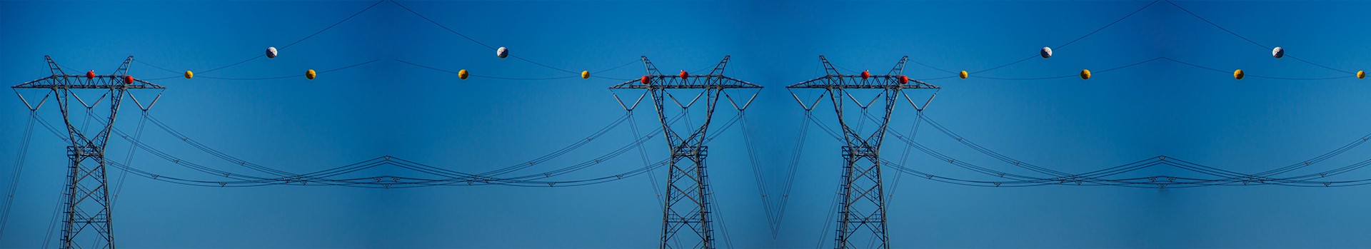
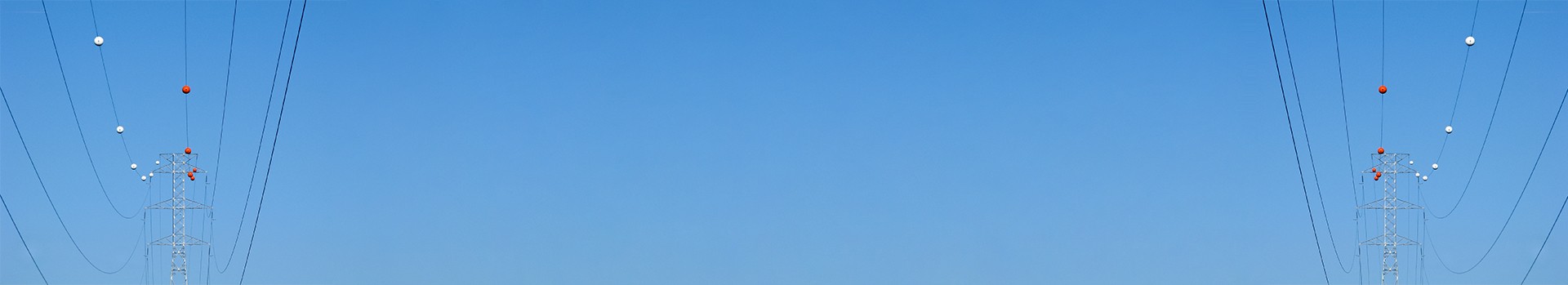
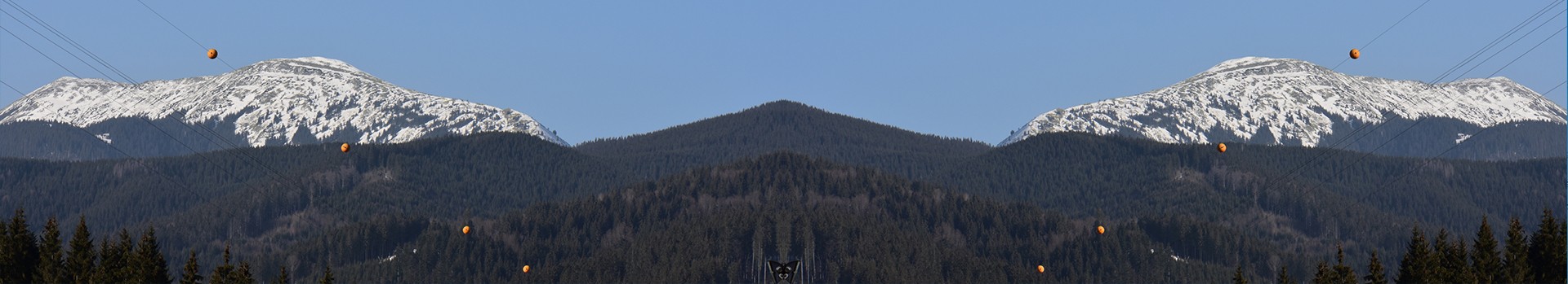
Warning spheres could be refered as Warning Balls or Warning Globes at different areas. The main idea to install them on overhead conductors, high voltage and transmisson lines to alert low flying airplanes and helicopters of the obstacle.
Warningsphere.com is your new guideline for all of your questions. You can find regulations, products and solutions.
Products
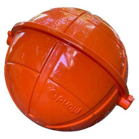
Warning Sphere
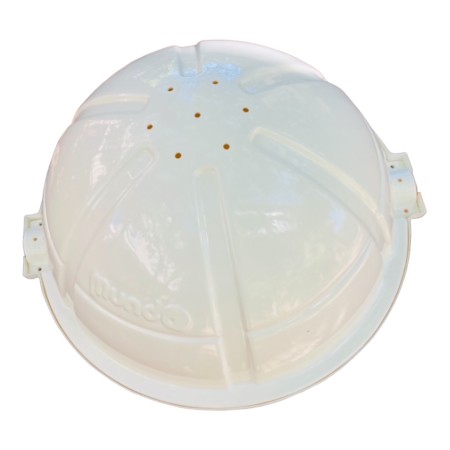
Mundo Warning Spheres are specially designed for marking all types of High-Voltage Lines, Transmisson Lines and Pylons. The main element of Mundo Warning Sphere is material Polyethylene. In comparison with a painted spheres, Mundo allows a stronger and longterm life.
A special design of our Warning Balls allows a single worker to easily install by hisself.
Mundo Warning Globes are well matched with the requirements of International Civil Aviation Organization (ICAO) guidelines for marking obstacles. Addition to this, in our product line has other models that are fulfill the requirments of FAA.
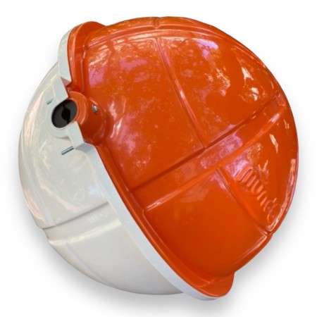
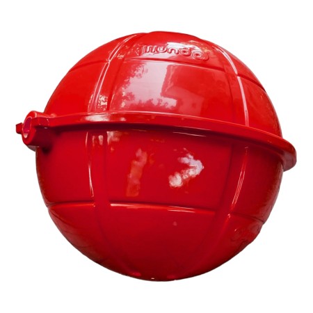
Basically four colors are aviable (white, red, orange and yellow). Even 60 cm diameter is the main size, 30-40-80-90 cm Warning Spheres are also aviable.
Mundo Warning Spheres comes with the special designed rubbers, which are required by the diameter of the wire. Means the same unit could be installed all diameter of wires just changing the rubbers.
Lastly Mundo Warning Spheres are not only robust and high quality products, but also with their short lead time and competetive price, it could be the best solution at this market.
Warning Sphere
Technical Characteristics
| Body Material | Composite |
| Color | Red, white, orange,yellow (others are optional) |
| Mounting | Rubber + stainless steel screws (included) |
| Diameter | 600mm (Other diameters avaiable) |
| Thickness | 2.5 mm |
| Weight | < 4 Kg |
| Temperature | -25°C à +65°C |
| Humidity | 100% |
| Frost | -50°C |
| Wind Speed | 260 Km/h |
| ICAO | Annex 14, Volume I, Chapter 6 |
| Quality | ISO 9001 ; 2008 |
| Warranty period | 3 years |
Warning Sphere
REGULATION
ICAO Annex 14 (Aerodrome Design and Operations)
6.2.5.4 Recommendation.— A marker displayed on an overhead wire, cable, etc., should be spherical and have a diameter of not less than 60 cm.
6.2.5.5 Recommendation.— The spacing between two consecutive markers or between a marker and a supporting tower should be appropriate to the diameter of the marker, but in no case should the spacing exceed:
a) 30 m where the marker diameter is 60 cm progressively increasing with the diameter of the marker to
b) 35 m where the marker diameter is 80 cm and further progressively increasing to a maximum of
c) 40 m where the marker diameter is of at least 130 cm.
Where multiple wires, cables, etc., are involved, a marker should be located not lower than the level of the highest wire at the point marked.
6.2.5.6 Recommendation.— A marker should be of one colour. When installed, white and red, or white and orange markers should be displayed alternately. The colour selected should contrast with the background against which it will be seen.
6.2.5.7 Recommendation.— When it has been determined that an overhead wire, cable, etc., needs to be marked but it is not practicable to install markers on the wire, cable, etc., then high-intensity obstacle lights, Type B, should be provided on their supporting towers.
FAA Advisory Circular:
3.5.1 Spherical Markers. Spherical markers are used to identify overhead wires and catenary transmission lines that are less than 69 kV. Markers may be of another shape, i.e., cylindrical, provided the projected area of such markers is not less than that presented by a spherical marker.
1. Size and Color.
The diameter of the markers used on extensive catenary wires (catenary wires that cross canyons, lakes, rivers, etc.) should not be less than 36 inches (91 cm). Smaller 20-inch (51-cm) spheres are permitted on less extensive catenary wires or on power lines below 50 feet (15 m) AGL and within 1,500 feet (458 m) of an airport runway end.
Each marker should be a solid color, specifically aviation orange, white, or yellow.
2. Installations.
a. Spacing.
Unlighted markers should be spaced equally along the wire at approximately 200-foot (61-m) intervals, or fraction thereof. There should be less space between markers in critical areas near runway ends [i.e., 30 feet to 50 feet (10 m to 15 m)].
They should be displayed on the highest wire or by another means at the same height as the highest wire. Where there is more than one wire at the highest point, the markers may be installed alternately along each wire if the distance between adjacent markers meets the spacing standard of 200 feet or less.
This method distributes the weight and wind-loading factors. (See Figure A-1 in Appendix A.)
b. Pattern.
An alternating color scheme provides the most conspicuity against all backgrounds. Unlighted markers should be installed by alternating solid-colored markers of aviation orange, white, and yellow.
Normally, an orange marker is placed at each end of a line and the spacing is adjusted [not to exceed 200 feet (61 m)] to accommodate the rest of the markers.
When less than four markers are used, they should all be aviation orange. (See Figure A-1 in Appendix A.)
c. Wire Sag.
Wire Sag, or droop, will occur due to temperature, wire weight, wind, etc. Twenty-five (25) feet (7.62 m) is the maximum allowable distance between the highest wire installed with marker balls and the highest wire without marker balls, and shall not violate the sag requirements of the transmission line design.
d. Adjacent Lines.
Catenary crossings with multiple transmission lines require appropriate markers when the adjacent catenary structure’s outside lines are greater than 200 feet (61 m) away from the center of the primary structure. (See Figure A-2 in Appendix A.)
If the outside lines of the adjacent catenary structure are within 200 feet (61 m) or less from the center of the primary structure, markers are not required on the adjacent lines. (See Figure A-3 in Appendix A.)